Home
Things to Know in Injection Moulding
Pitfalls in Injection Moulding
Myth in Injection Moulding
A Guide to Injection Moulding of Plastics
Foreword
Preface
Contents
Summary
Archives of Articles by Prabodh C. Bolur
Selection of IM Machine
Technological Solutions
Technological Tools
Engineering Basics for Injection Moulding Machine
PlastIndia Photos
Useful Links
Author
Contact Author
Millineum's MoldFlow User Meet
Answers to YOUR Questions
|
Q : What is the reason for more output in screws with higher LD ratio. In what
manner a screw with higher LD ratio is beneficial to a processor in terms of productivity?(From : Gopal )
A: Please go through my book " A Guide to Injection Moulding of Plastics" on page 31 to page 36. Increasing L/D ration does
not increase output of the screw for a given rpm.
Please visualise the following;
- Feed zone promotes out put rate.
- Every rotation of screw pushes the materials - in granule form- by one pitch in feed zone.
- Material dropped by gravity on the screw channel is swallowed by the screw at the rate of RPM of screw multiplied by the channel volume per
pitch at feed zone.
- Channel volume at feed zone is not fully occupied by the material because of inevitable space between granules.
- Higher the diameter of screw, higher channel volume per pitch, hence higher the out put.
Now it should be clear that cannel depth of screw at feed zone and the diameter of screw influences the output of screw.
Now try to understand the logic of increasing L/D ratio.
- Increased L/D ratio increases the residence time for material in screw.
- Suppose we get best melt condition at certain screw rpm say N1 on a lower L/D ratio screw. N1 correspond to certain residence time for material
in the screw.
- Therefore it should be possible to get the same melt condition by rotating the larger L/D ration screw at higher rpm (more than N1) to maintain
a desired residence time. By doing this, its output increases. Here increase in out put is not because of increased L/D ratio but because of possibility of increasing screw rpm, which is possible for
thermally stable materials only.
- However, increased screw rpm increases the shearing rate on the melt in compression zone. This can be acceptable for thermally very stable
commodity polymers like HDPE, LDPE, PP, PS etc.
- But increased shearing is not acceptable for engineering polymers. Therefore screw rpm for a given polymer and for a given screw diameter, is
limited by its sensitivity to shearing. You will observe this in the recommendations of the polymer manufacturers. They specify limiting screw rpm for a typical screw diameter or they specify
limiting velocity (0.05m/sec to 0.3m/sec) of the screw at its periphery.
Therefore it could be concluded that
- Higher L/D ratio screw is good for fast cycling thin walled mouldings of commodity polymers. Fast cycling would not be possible by lower L/D
ratio screw as the materials will require certain minimum residence time to cook its melt properly. Fast cycling is possible because of efficient cooling circuit in the mould as well as water flow
system in the factory. In most of the factories the water flow per mould (per cooling channel) is not adequate. There are lots of myth in this regards. People select pump based on pressure, but it
should be based on flow rate required per channel in the mould. Each channel requires 15 liter/min.
- For processing engineering polymer, increased L/D ratio can not be helpful. Now with the availability of software for designing screw, it should be
possible to get optimum screw design on computer before it is machined. There fore development time for screw is very much reduced. However the awareness of different requirements for commodity and
engineering polymers is quite poor in the industry.
Since thin walled disposable items are a huge business in Europe and USA, You will notice the trend for increased L/D ratio.

Q: We have imported one mould, whose width dimension is 10mm more than the horizontal clearance between tiebars of our injection-moulding
machine. Can we cut the mould plates in such a way to accommodate the mould on the machine platen?
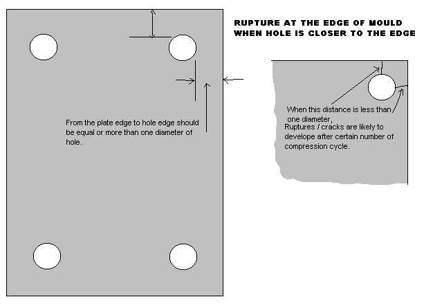
A: You must ensure, the distance from the mould plate edge to guide pin bore edge is equal to or more than one diameter of
bore diameter (guide pin). If this distance is less than one diameter, then repeated compression of mould during mould clamp can cause rupture between plate edge and bore edge after number of cycle
of compression. In other words, the life of the mould could be limited to occurrence of this rupture.
It is better to fix this mould on another machine with larger platen and clearance between tie-bars. If you do not have next sized machine, then you decide to machine
the plates to lower size, then you are compromising on the life of mould.
The option of reducing the mould plates’ size may be worth if the cost of mould is much lower than the cost of machine, or production required from this mould
is not very high enough to warrant the investment in new bigger platen machine. If huge quantity of moulding required from this mould than, it is better to invest in new machine of correct
specification.

Home, Introduction, Foreword, Preface, Contents, Summary, Useful Links,
Author, Contact Author
 You must have your personal copy of this book,
if you are concerned with plastics molding,
Order your copy NOW.
|