|
|
|

|
UNDERSTANDING SELECTION OF INJECTION MOULDING MACHINE |
|
Home Things to Know in Injection Moulding of Plastics Pitfalls in Injection Moulding Myth in Injection Moulding A Guide to Injection Moulding of Plastics Archives of Articles by Prabodh C. Bolur Selection of IM Machine Engineering Basics for Injection Moulding Machine PlastIndia Photos Useful Links Author Contact Author Millineum's MoldFlow User Meet Answers to YOUR Questions  |
INTRODUCTIONPlastic Injection Moulding process demands precise control of melt temperature, melt viscosity, injection speed, injection follow-up pressure, switch over point from speed to pressure, cycle time. It is found that different polymers have different characteristics and different limitations in processing. Shear rate and shear stress influence melt temperature, viscosity, density and flow behavior of polymer. Some polymers are hygroscopic, some polymer have limited thermally stable time which is different at different temperature. Such polymers have limited residence time. The changes in each parameter has its own influences on other parameters. Hence, process control becomes very intricate. This calls for critical analysis of the machine specifications and capabilities while ordering the machine. While selecting injection moulding machine the following specifications are required to be evaluated.
MAXIMUM SHOT WEIGHT, MAXIMUM SWEPT VOLUMEThe shot weight of the mould (part & runner system) should be lower than the maximum shot weight of the machine for a given polymer. The maximum shot weight of the polymer can be determined by multiplying the density of polymer at moulding temperature by the maximum swept volume (in cc) of the machine. The characteristic of specific volume (cc/g) v/s temperature should be referred to obtain the density at moulding temperature. (Refer table) The shear sensitive polymers like CA, POM, PMMA, PPO, PA, PBT, RPVC,, SAN etc have limited permissible residence time. It may be observed that
Higher percentage utilisation of injection capacity can reduce the residence time thereby maintaining it well below the permissible level. K x cycle time x 100 Min.% utilisation of injection capacity =------------------------- -------------- permissible residence time Therefore actual %age utilisation of injection capacity should be more than minimum % utilisation. Permissible residence time has to be lower than thermal stability time. METERING STROKEMaximum metering stroke available on the machine and percentage utilisation of maximum shot volume of the machine has important influence on processing and quality of moulded parts.
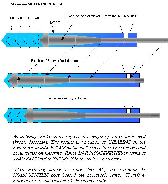
In 1980s the metering stroke used to be around 3.5 to 3.75 of screw diameter i.e s:D ratio. By 1987 the s:D ratio increased to 4.2. Now Italian machines have even higher ratio of over 4.5. Even higher ratio are also available. Higher ratio is not helpful in processing. Streaks and air bubbles appear on the moulding on account of excess s:D ratio. It can be observed that effective screw length - from non return valve to the feed throat - decreases as the metering stroke increases. It is maximum (- as specified L/D ratio of 18 to 23 -) when screw tip is at fully forward position ( metering stroke is zero) and it becomes minimum when maximum metering stroke is reached. The granules entering ( from feed throat ) the screw fall into the middle (approximately) of the feed zone at the end of metering stroke. These materials will obviously have to travel less to reach the nozzle through compression and metering zone. Whereas the materials entering the screw at the beginning of metering stroke - after injection stroke - have to travel longer path with in the screw to reach nozzle. It means that amount of heat absorbed by the material due to conduction from heater and shearing in compression zone will not be constant but it will be varying from maximum to minimum. Therefore a temperature & viscosity gradient is introduced along the axis of the screw. This results in inhomogeneities in melt causing quality problem in moulded parts when metering stroke is more than 4D. Therefore, inspite of available maximum shot volume corresponding to maximum stroke of say 4D or 4.5D, only maximum shot volume of 3D to 3.5D should be considered while selecting the machine. The following formula can be used to convert the stated shot weight to applicable shot weight. Applicable shot weight = ( 3 / s:D ) . Stated shot weight
FREEZING TIME & INJECTION TIMEInjection time is related to injection rate (cc/sec.) and injection rate should be high enough to avoid freezing of melt during filling phase. Higher injection rate does not affect the thermally stable commodity polymers like HDPE, LDPE, LLDPE, PP, PS ect. The higher injection rate can be limited on account of sensitivity of polymer to shearing while passing through narrow passages (especially for engineering polymers). Freezing time is proportional to cube of minimum wall thickness. Generally injection time is also proportional to square of wall thickness. MAXIMUM INJECTION SPEEDModern injection moulding machines are equipped with variable delivery or multiple pumps which are capable of delivering sufficient oil to injection hydraulic cylinder to give high enough injection speed for filling mould cavities rapidly. Further, higher injection speed can be achieved by the use of hydraulic accumulator (normally offered as optional). Higher injection speed can push the melt to furthest part of mould at shorter time before the freezing of melt (increase in melt viscosity) on account of lower mould temperature. During filling phase, injection speed is required to be under control with out disturbing the pressure setting. Therefore,set pressure has to be higher than actual pressure so that the relief valve is not actuated. On actuation of relief valve, there would be no control on injection speed. Thin walled commodity plastics items can be moulded with high injection speed. Shear sensitive engineering polymers are likely to be overheated on account of excessive shearing due to high melt velocity. Hence, injection speed will have to be limited to suit the polymer characteristics. In modern machine injection speed can be set in multi stages - stroke controlled (up to 10 stages).
MAXIMUM INJECTION PRESSUREThe injection pressure is required to overcome the resistance to flow of melt in the mould. It depends on melt viscosity,flow ratio and mould temperature. Set pressure is higher than actual pressure during filling phase. The relief valve is actuated on reaching set pressure during pressure phase. Higher injection pressure is required for processing high viscosity materials like PC, RPVC, TPU ect. At present new generation machines are capable of giving maximum injection pressure of 2200 bar or even 2500 bar. Injection units are normally offered with the option of three screws (A, B & C) of different diameter. A screw (lower dia) gives maximum injection pressure of around 1800 - 2400 bar. B screw (medium dia) gives maximum injection pressure of around 1800 - 1500 bar with max. shot weight/volume higher than that of A. C screw (higher dia) gives maximum injection pressure of around 1500 - 1300 bar with max. shot weight/volume higher than that of B. Screw A is recommended for moulding
Screw B is recommended for moulding · engineering parts of lower flow ratio with high viscosity polymer.· commodity items of medium flow ratio with medium wall thickness in commodity polymer.Screw C is recommended for moulding
It should be noted that the maximum flow ratio of the part to be moulded should be lower than the maximum possible flow ratio of the polymer at the maximum injection pressure of the injection unit. Refer the table for maximum flow ratio of various polymer. INJECTION POWERMaximum linear injection speed in mm./ sec. decided by pump's flow rate and piston area of hydraulic injection cylinder. Maximum linear speed mm/sec. = Flow rate of Pump / piston area of hyd. inj. cylinder. Normally every machine manufacturer offers the option of 2 or 3 screws of different diameter. The injection unit is designed for a certain maximum injection power. Max.Injection power ( Kg-cm. / sec) = Max. Injection Pressure x Max. Injection rate (cc / sec). Therefore, maximum Injection power remains constant for 2 or 3 sizes of screw offered as optional with the Injection unit. It should be noted that as diameter of screw increases, maximum rated injection pressure reduces and maximum injection rate increases. Screw's L/D ratio is normally designed for middle size of the three sizes of screw. Therefore, L/D ratio of lower diameter screw would be higher and higher diameter screw would be lower. It should be realised that the biggest possible size of the item that can be moulded on a given platen area under a given clamp force from commodity plastics depends on maximum injection power available on a given injection unit. It is the Injection power which is responsible for spreading the melt into the mould cavity. Lower powered injection unit can not be able to spread or move the melt to the boundary in all direction before melt looses its fluidity on account of continuous cooling of mould. As melt cools it looses it's fluidity and it's viscosity increases, thereby demanding more pressure and hence more clamp force and also more consumption of power. This results in moulded-in stress in the moulded part which is not desirable. Such parts fail due to stress cracking while in use.
PLASTICISING RATEIt is the maximum rate at which polymer (Polystyrene) is plasticised. It is given in terms of Kg/hr or grams per second. The time taken to plasticise the given quantity of polymer can be calculated. It should be possible to complete the plasticising of shot weight within cooling time which can be estimated from the following formula. Cooling time = Cc x (max. wall thickness mm)2 Cc = 3.5 to 5.5 for PS 1.9 to 4 for ABS 3.05 to 5 for POM 1.4 to 3.5 for PA6/6 2.0 to 4 for LDPE The constant will also dependent on design of cooling channels in mould and it's effectiveness. In actual practice it will be more. Latest machines provide screw rpm and reaction pressure settings (both) in 3 to 5 stages. It helps in improving precision of moulding.  Next Page Next PageTechnical Papers by Prabodh C. Bolur Understanding Energy Consumption in Injection Moulding Machine(1994)Understanding Heat Exchange in Injection Moulds (1994) Ideal Moulding Shop (2001) Understanding Selection of Injection Moulding MachineThis paper was part of authors lectures at CIPET since 1980. It has been regularly updated. Technological Solution to Injection Moulding of Plastics (1999) Technological Tools for Part Design, Mould Design and Mould Fabrication (1999) Extrusion of Thermoplastics(1998) Archives. Home, A Guide to Injection Moulding of Plastics, Archives of Articles,Usefullinks.  if you are concerned with plastics molding, Order your copy NOW. |
|||||||||||||||||||||||||||||||||||||||||||||||||||||||||