|
|
|

|
Engineering Basics for Injection Moulding Machine - Prabodh C. Bolur |
Home Things to Know in Injection Moulding Pitfalls in Injection Moulding Myth in Injection Moulding A Guide to Injection Moulding of Plastics Foreword Archives of Articles by Prabodh C. Bolur Selection of IM Machine Engineering Basics in Injection Moulding Machine PlastIndia Photos Useful Links Author Contact Author Millineum's MoldFlow User Meet Answers to YOUR Questions  |
ENERGY Energy is capacity to do work. Work is done when a force moves its point of application in the direction of force. = force x distance moved. Power is rate of doing work. Power = force x (distance/time). This also called energy. Energy can neither be created nor destroyed but only transformed from one form to others. MACHINE A machine is a device that makes the work easier.
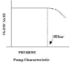
Machine can not create energy by it self. Therefore, machine requires a prime mover. In most of the machines prime mover is an Electrical motor - 3 phase squirrel cage Induction motor in case of Injection Moulding Machine. In this machine electrical energy is converted to mechanical energy through hydraulics. PRIM-MOVER Electric motor is coupled to hydraulic pump. Pump has flow rating -say 100 liters per min. or 25 gpm. Pump delivers oil flow in the system. Oil flow meets resistance causing resultant pressure in the system. The hydraulic system includes Relief Valves for pressure limit, Flow control Valves for speed and Directional valves for directing oil to Actuators - Cylinder for linear movement and Hydromotor for rotary movement. For each to and fro movement there must be one cylinder as actuator. Therefore there are cylinders for mould open/ close, injection unit forward / retract, Injection / retract. And Hydro-motor for screw rotation, PUMP Pump delivers oil flow in the system at rated flow rate till the resistance reaches say 150 bar. Thereafter further increase in load pressure decreases the flow rate. Many in the moulding shop floor wrongly believe that pump creates pressure. Pump creates flow rate not pressure. Therefore, hydraulic system pressure is not allowed to go beyond 150 bar by Main Relief Valve in the system.
PRESSURE The melt is pushed by the screw tip through nozzle in to the mould. As the melt moves inside the mould, resistance to flow builds up and hence melt pressure at screw tip increases. This is reflected at the hydraulic pressure gauge at injection hydraulic cylinder. Here, Ps As = Ph Ah Ps is pressure at screw tip in barrel and Ph is hydraulic pressure at injection hydraulic cylinder. As is cross section area of screw and Ah is cross section area of piston of injection hydraulic cylinder Therefore pressure at hydraulic cylinder would be Ph = (As/ Ah) Ps . Since (As/ Ah) is less than one, Ph would indicate lower value of pressure than Ps. Similarly Ps can be determined = (Ah / As) Ph. (Ah / As) is called Intensification Ratio. It should be noted that melt pressure is
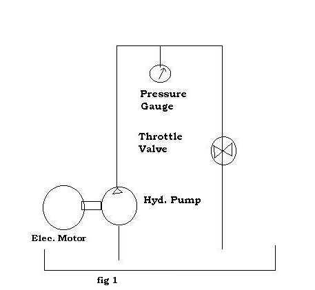
SPEED Injection rate = As V cc/sec. Injection rate is available in the spec table Here velocity V of screw is same as velocity of hydraulic piston of injection cylinder. On hydraulic side AhV = oil flow rate at hydraulic cylinder. Ah is normally does not appear in the machine specification table. However, Max pressure rating (say 1400 bar) at screw is available under Injection Unit spec. Most of the hydraulic system pressure is recommended to limit at 150 bar. Therefore 150 bar can be considered as max hydraulic pressure corresponding to max melt pressure. Now it is possible to compute diameter or area of injection piston if required. POWER POWER= F V =(F/A) (AV) =P Q F is force and Q is flow rate Max Work that can be done by the machine with out accumulator = =(max. melt pressure) x (max injection rate) It means for a given screw diameter, higher injection rate means higher power and hence higher hp of electric motor. In injection moulding power consumption is not constant but it is cyclic. Pressure peak occurs for a short duration. Moreover during peak load after switchover point, flow rates are lower. Therefore, machine manufacturer may use slightly lower hp electric motor, which can sustain short peak load. Thin walled injection moulding demand higher injection rate at higher pressure. Therefore power consumption has to be higher than that of medium or thicker walled moulding. EFFICIENCY Efficiency of the machine is defined as the ratio of work output to wok input. It can not be one. It has to be lower than one to account for power losses due to friction and other causes. Efficiency of various types of hydraulic circuit is discussed in the book " A Guide to Injection Moulding of Plastics". UNDERSTANDING OF "PRESSURE", To check the understanding of "pressure", consider fig 1 and answer the following questions.
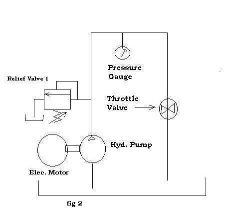
Now consider fig 2. A relief valve 1 is added to the circuit and it is set for 150 bar pressure.
Now consider fig 3. Another relief valve 2 is added to the circuit and it is set at 80 bar. Relief valve 1 is set at 150 bar.
To check the answers click here. See Myth in Injection Moulding click here
PREVIOUS -Extrusion NEXT -USEFUL LINKS Technical Papers by Prabodh C. Bolur Understanding Energy Consumption in Injection Moulding Machine(1994)Understanding Heat Exchange in Injection Moulds (1994) Ideal Moulding Shop (2001) Understanding Selection of Injection Moulding MachineThis paper was part of authors lectures at CIPET since 1980. It has been regularly updated. Technological Solution to Injection Moulding of Plastics (1999) Technological Tools for Part Design, Mould Design and Mould Fabrication (1999) Extrusion of Thermoplastics(1998) Archives. Home, A Guide to Injection Moulding of Plastics, Archives of Articles,Usefullinks.  if you are concerned with plastics molding, Order your copy NOW. |