|
|
|

|
UNDERSTANDING ENERGY CONSUMPTION IN INJECTION MOULDING MACHINE |
|
Home Things to Know in Injection Moulding Pitfalls in Injection Moulding Myth in Injection Moulding A Guide to Injection Moulding of Plastics Foreword Archives of Articles by Prabodh C. Bolur Selection of IM Machine Engineering Basics for Injection Moulding Machine PlastIndia Photos Useful Links Author Contact Author Millineum's MoldFlow User Meet Answers to YOUR Questions 
|
Overview of energy consumption becomes necessary so that the moulders can evaluate the real economics of production in a moulding shop. Injection moulding is a cyclic process with variation of load through-out the cycle. The variation of the load depends on several factors of the part design (to be moulded), polymer used and process parameters set. Therefore presentation of overview becomes quit complex. POWER CONSUMPTION The Injection moulding process involves
The polymer demands specific Kilo-Calories of heat for changing its state from solid to melt. The required heat comes from
The melt is injected in to the mould at a flow rate and at a varied pressure. The power consumed during injection is proportional to -
The heat is drained off through the water circulating in the mould during cooling period. The power is also required for the various movements in the machine.

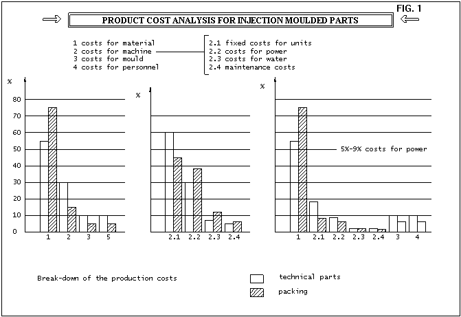
PRODUCT COST ANALYSIS On analysing cost of moulding-production of injection moulded parts it is observed that- ( see fig. 1)
On further analysing the cost of machine which is only 30% / 25% of the total cost of production, it is observed that-
Therefore power cost is hardly between 5% and 9% of total moulding (production) cost whereas the material cost is 50 to 75 % of total cost. It is more economical to reduce the wall thickness in order to reduce the cost of the product. Reducing wall thickness would mean more injection rate and injection pressure and hence increase in power consumption slightly. Injection moulding machine is actuated by hydraulic system which has electrical three phase A.C induction motor as prime mover. Therefore in the machine electrical energy is transformed in to mechanical energy through hydraulic energy. The energy reaches the actuators in the form of pressure and volume flow. While transmitting power through hydraulic the loss of energy could be due to flow losses and friction. The compression of hydraulic oil develops frictional heat which has to be controlled by radiation or cooling. 
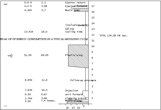
BREAK-UP OF ENERGY CONSUMPTION If we analyse power consumption in a typical moulding cycle the break up of power consumption would be as follows. (See fig. 2)
This typical energy consumption in a moulding cycle may differ slightly depending up on the following-
POWER UNIT An electrical A.C three phase induction motor converts electrical energy in to mechanical energy. This motor drives the pump to provide volume flow to withstand load pressure. Electrical Motor's efficiency is 0.87 as per the manufacturer. For a constant delivery pump Q (calculated) = 112.6 l/min. Q (actual) = 98 l/min. efficiency = 0.81 Therefore conversion efficiency from electrical motor to hydraulic flow is 0.87 x 0.81 = 0.70 It means that input of 37 kW from electrical motor gives an output of 26 kW at the hydraulic pump. The following combinations of pump-motor are in use today in hydraulic system of injection moulding machine. Three phase induction motor with the
PUMP The energy efficiency depends on the
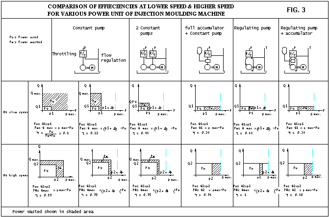
Consider a hydraulic cylinder whose piston has to be moved first half of the full stroke (S1) at lower speed and remain stroke (S2) at higher speed. It is well known that flow rate determines the speed and pressure determines the force in hydraulics. (See fig. 3) Let V1 be the slow speed and P1 be the corresponding pressure and S1 be the corresponding stroke. Let V2 be the higher speed and P2 be the corresponding pressure and S2 be the corresponding stroke. We shall analyse the energy consumption separately for slow and high speed movement of piston. It can be seen that the most favorable efficiency is achieved with regulated variable delivery pump while operating at high speed-stroke S2. We shall consider it's efficiency as 1 for comparison purpose. The efficiencies of all other power units will be lower than 1. 
We can now observer the following. (See fig. 3)
p(max.)/p(req.)= 1
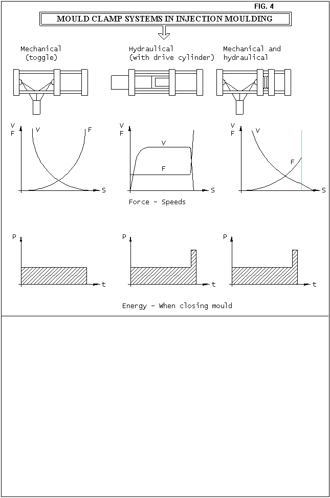
CLAMP SYSTEM Toggle , Fully hydraulic and combination of mechanical and hydraulic clamp systems are available. Toggle clamp, as it is claimed, offers 10% saving in the power consumption as a result of shorter stroke of mould closing cylinder and harmonic movement. This advantage should be weighed against following aspects of the toggle clamp.

A saving of 10% of energy cost (which -energy cost- in turn is merely 30% of production cost ) works out to hardly 0.9 % of production cost. This is absolutely negligible considering the other aspects of toggle system and advantages of hydraulic system. Hydraulic clamp system offers further advantages-
SCREW DRIVE The screw converts granules in to melt and acts like a melt pump. The screw is required to be rotated to carry out it's function. It can be coupled
Since electric motor can not be switched ON and OFF frequently at the interval of a cycle time it requires a clutch which engage and disengage during the moulding cycle. Hence electric motor would be running idle during non-plasticising part of the cycle. Therefore the advantage of efficiency of electric motor is lost. Hydraulic motor drive for screw is most suitable because of its compactness and ease of RPM regulation. This advantage overcomes the disadvantage of less efficiency on account of leakage losses in the motor. PLASTICISING OF POLYMER The heat required to melt the polymer depends on its specific heat property. The heat is also produced by shearing action in the compression region of the screw. Screw design could be optimised to get homogeneous melt at lowest possible uniform melt temperature. Considerable heat loss could be prevented by proper insulating the heaters ( ceramic insulation). In addition to this screw- barrel assembly can be covered to keep the radiation losses as low as possible. Specific energy consumption (Watt-sec/Gram) is the ratio = energy consumed per moulding cycle / weight of moulded part in grams. This ratio could be maintained as low as possible provided efficiency aspects of machine selection, pump and controls are understood while setting the machine. CLASSIFICATION OF PARTS TO BE MOULDED Wall thickness and flow ratio are very are important while evaluating the machine specification and cycle time. Therefore we can classify the parts -to be moulded - on the basis of wall thickness.
CLASSIFICATION OF MOULDED PARTS - BASED ON WALL THICKNESS - TABLE
THIN WALLED PARTS Most common items of thin wall are disposable cup and packaging items and disposable syringe. They are normally moulded from easy flowing PP. Applications in Telecommunication and Computer industry also growing on account of lowering in size and weight of portable items like Cellular phone, Laptop and Note book computer. Materials used in theses items are PC, PC/ABS, Mod.PPO. These materials have high heat resistance, high impact strength and good electrical properties. Hence lower wall thickness resulting in lower weight is advantageous in portable equipments. The lower than 1 mm wall thickness does not permit the longer flow path. Lower than 1 mm wall also demands fast filling to prevent freezing while passing through the cavity. This is because freezing time is proportional to cube of wall thickness. Therefore high speed (rate) filling during filling phase is required. Since thin walls offer high resistance to flow, filling also takes place at higher pressure. The pressure peak is reached during filling phase when filling rate-speed- is higher. The product of speed and pressure is high during the filling phase. The pressure during pressure phase is just enough to avoid moulded in strain. The speed at pressure phase should be set low enough just to transmit the pressure. The power consumption during pressure phase is quit normal. Power consumption is of highest order for parts with thin wall and higher flow ratio. Such items require accumulator assited injection speed. Hence FR or FM or equivalent machines are most suitable. You might have noticed larger runner thickness than the thin wall thickness of the part. In such cases the cooling time has to accommodate cooling of runner system. If the flow ratio becomes high then multiple gates are to be located so that the longest flow ratio from each gate falls with in the maximum permissible flow ratio of melt. Hot runners can reduce cooling time and hence cycle time. It is desirable to ensure injection capacity utilisation of less than 50% for fast cycling thin walled parts of commodity plastics. It also becomes necessary to check wether the plastisising capacity is adequate to finish the dosing during cooling time. In case of engineering materials, percentage utilisation of shot capacity of the machine should be more than 30-35%. Otherwise higher residence time may cause degradation of polymer melt. PARTS WITH MEDIUM WALL THICKNESS Most of the injection moulded items have wall thickness between 1 mm and 2 mm. The larger flow length becomes possible with in the limitation imposed by flow ratio characteristics of the given polymer melt. Injection speed required is not as high as that in thin walled parts. The cavity pressure builds up as the cavity gets filled up to about 80 % or so. Therefore set pressure is not reached during filling phase. The set pressure is reached during pressure phase which is just low enough to avoid moulded in strain. The high speed and pressure do not occur at the same time. Hence actual power consumption is quite lower than the connected power. Medium power unit is to be recommended. PARTS WITH LARGER WALL THICKNESS Most common items of large wall thickness are pipe fittings, textile bobbins, etc. Screw driver handle, handles for appliances etc. are also of very large thickness. The melt can be pushed to longer flow path when wall thickness is large. Freezing time is also more and hence high injection speed is not required. The pressure build up in the cavity is slow and set pressure is reached only during pressure phase. The set speed during pressure phase should be low. Therefore speed and pressure never peak simultaneously. Presssure peak is reached during pressure phase when injection rate is low. Hence connected power can be lowest for larger walled parts. Lower connected power should be recommended for such thick walled moulding application. The large parts with large flow ratio require multiple gates so that the longest flow ratio from each gate is lower than the maximum permissible flow ratio. INJECTION CAPACITY UTILISATION Engineering polymers normaly have limited thermal stability whereas comodity plastics like HDPE, LDPE, PP, PS have good thermal stability. While selecting injection unit for engineering polymers it's sucesseptibility to thermal degradation should be copnsidered. Hence in the absence of information about thermal stability of polymer, it is safer to select the injection unit with 35% to 75% utilisation of injection capacity for moulding engineering polymers. While selecting injection unit for fast cycling parts (< 8 sec) injection capacity utilisation should be lower than 50%. ( or 55%.) This is to allow sufficient residence time for melt to come to desired condition. SUMMERY It is now clear that to produce plastic moulded parts with minimum energy consumption the following facts should be understood.
( p + a ) ( v - b ) = R T / M b and M constants.
NEXT -Heat Exchange / cooling in moulding Technical Papers by Prabodh C. Bolur Understanding Energy Consumption in Injection Moulding Machine(1994)Understanding Heat Exchange in Injection Moulds (1994) Ideal Moulding Shop (2001) Understanding Selection of Injection Moulding MachineThis paper was part of authors lectures at CIPET since 1980. It has been regularly updated. Technological Solution to Injection Moulding of Plastics (1999) Technological Tools for Part Design, Mould Design and Mould Fabrication (1999) Extrusion of Thermoplastics(1998) Archives. Home, A Guide to Injection Moulding of Plastics, Archives of Articles,Usefullinks.  if you are concerned with plastics molding, Order your copy NOW. |