|
|
|

|
UNDERSTANDING SELECTION OF INJECTION MOULDING MACHINE |
|
Home Things to Know in Injection Moulding of Plastics Pitfalls in Injection Moulding Myth in Injection Moulding A Guide to Injection Moulding of Plastics Foreword Archives of Articles by Prabodh C. Bolur Selection of IM Machine Engineering Basics for Injection Moulding Machine PlastIndia Photos Useful Links Author Contact Author Millineum's MoldFlow User Meet Answers to YOUR Questions  |
Continued from previous page. CLEARANCE BETWEEN TIE BARS AND PLATEN SIZEThe dimensions of shut mould should be such that it should be possible to pass through the clearance between tiebars and it should be possible to accommodate the mould on platen of the machine. Therefore, one dimension should be less than the clearance between tiebars and another dimension should be less than the platen size. Enough space should be made available to accommodate the clamps if direct bolting of mould on the platen is not provided. The moulds should not be smaller than 0.7 times the clearance between tiebars. Smaller moulds if used at full clamping force are likely to give unfavorable platen deflection harmful for platen and tiebar life. 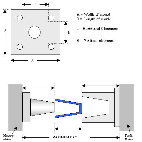
MAXIMUM DAYLIGHTThe shut mould height of the mould should be less than 1/3rd of maximum daylight so that there should be enough room for the ejection of part when mould platen is fully opened. If it is closer to 1/3rd of maximum daylight then the clearance between core and cavity of mould in fully open position should be verified on the drawing board. The maximum daylight has to accommodate height of moving half of mould, height of moulded part, minimum and enough clearance for removal of moulded part and height of fixed half of mould. With Hydraulic clamp machine, Maximum daylight = Minimum mould height mould open stroke. If shut mould height is more than minimum mould height of machine then the mould open stroke is reduced to the extent of difference in shut mould height of mould and minimum mould height of machine. In case of Toggle machine, Maximum daylight = Maximum mould height Mould open stroke. Mould open stroke remains constant in toggle machine.
MOULD OPEN STROKEIt should be 2 to 2.5 times the part height so that there is enough room to remove the part.
MINIMUM MOULD HEIGHTWith hydraulic clamp machine there can be only one specification of mimimum mould height. However, with toggle clamp machine, the shut mould height has to be between minimum mould height and maximum mould height of machine. If the shut mould height is lower than the minimum mould height of the machine then the additional back plate of suitable thickness should be provided on the mould to build up the shut mould height equal to more than the minimum mould height of the machine.
CLAMPING FORCEThe clamping force should be greater than the cavity force in the mould, i.e., mould opening force exerted by the melt in cavity. The cavity force depends on injection pressure and projected area of moulded part. Injection pressure depends on maximum flow ratio of part and melt viscosity. The flow ratio of part depends on geometry of part and location of gate. Viscosity depends on characteristic of polymer. It is necessary to calculate
CLAMPING FORCEIt is necessary to calculate · projected area· most prevailing wall thickness· flow ratio =L1/T1 L2/T2 L3/T3where L1 = length of flow in section 1 T1 = wall thickness in section 1 and so on.
The mould cavity pressure can be determined as explained earlier under Contol of parameters on machine. Clamping force > (cavity pressure) x (projected area) CAVITY PRESSUREThe table gives the cavity pressure for a given flow ratio at a given wall thickness ( most predominant wall thickness). This table also gives the multiplication factor for different polymer melt. CAVITY PRESSURE FOR THERMOPLASTIC MELT WITH VARIOUS FLOW CHARACTERISTICS- TABLE
Multiply the cavity pressure obtained from the above table by the following factors for different thermoplastics.
Cavity pressure obtained from the above table when multyplied with the projected area gives the cavity force. The clamp force should be about 15% higher than the cavity force. COOLING TIMEIt can be observed that the largest portion of cycle time is cooling time which is proportional to square of maximum wall thickness and also efficiency of cooling set up. Therefore for faster production, wall thickness has to be low and efficiency of cooling system in mould as high as possible. HYDROMOTORThe option of high torque, medium torque and low torque hydromotor is now available. Normal (medium torque) hydromotor can be suitable for moulding most of the polymers with the exception of high viscosity polymer like PC, RPVC, PPO, TPU, etc. High viscous polymers need high torque hydromotor. Low torque hydromotor can be recommended for the commodity plastics with thicker wall thickness. By adopting right type of hydromotor for specific application the melt at right temperature can be obtained and the power consumption can also be minimised.  Previous page / Next page Previous page / Next page Technical Papers by Prabodh C. Bolur Understanding Energy Consumption in Injection Moulding Machine(1994)Understanding Heat Exchange in Injection Moulds (1994) Ideal Moulding Shop (2001) Understanding Selection of Injection Moulding MachineThis paper was part of authors lectures at CIPET since 1980. It has been regularly updated. Technological Solution to Injection Moulding of Plastics (1999) Technological Tools for Part Design, Mould Design and Mould Fabrication (1999) Extrusion of Thermoplastics(1998) Archives. Home, A Guide to Injection Moulding of Plastics, Archives of Articles,Usefullinks.  if you are concerned with plastics molding, Order your copy NOW. |